
“An ATmega8 acts as a controller for 8 EEPROM chips, letting other devices store data on it, such as config files and logs, via UART or USB.
A Common Problem
Normally, SD cards are used to store large amounts of data when logging information or retrieving files. However, SD cards have slow access times and require 4 GPIO pins, along with more software overhead. When using microcontrollers that are short on RAM and/or GPIO pins, such as the ATtiny family, storing large amounts of data while keeping a program small can be a large issue.
To solve this, I wanted to construct an SSD that could mimic the functionality of a conventional one. Commonly found SSDs are comprised of a controller, flash chips, and sometimes a bit of DRAM that acts as a cache. At the most basic level, the onboard controller takes in a command via a protocol like SATA and then decodes it to then read or write data. The flash chips are connected to the controller, and they can be read from or written to. My SSD would have an ATmega8 as its controller, along with several EEPROM chips.
The Components
In order to build a storage solution, I first had to decide what IC to use to store data on. Since EEPROM chips are cheap and easy to interface with, I went with eight 24C02C’s, which are each 2Kb (256 bytes) large.
The chips also operate at 5v, eliminating the need for any logic level conversion between the controller and EEPROM. Since I wanted the “SSD” to also communicate over USB, it was necessary to add a CH340G USB to UART converter.
This would let data be read from the device on a PC with a python program.
Designing and Creating a PCB
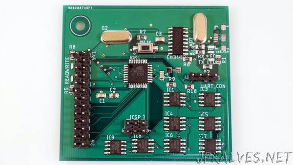
As with most projects, it began with a simple sketch on paper. I laid out the rough locations of the components, such as grouping the eight EEPROM chips together and placing the CH340G close to the ATmega8. Then I moved onto creating the schematic.
Each LED got a 220 ohm resistor to limit the current it uses. They are connected to the UART lines, 5v, and PD2 / PD3. I also added a couple of pin headers that break out either the UART bus or most of the pins for easy debugging.
Assembling the Board
An SMT stencil is a panel that has cutouts for SMD pads.
Solder paste gets applied evenly across it, and then the stencil is lifted, revealing a nice layer of precisely applied paste below.
Next, I used tweezers to place each component into its respective location by using the silkscreen labels and the design in Eagle as references. Lastly, the board went into a toaster oven and baked until the solder paste had reflowed.
Structuring Data
You have probably heard of filesystems, such as NTFS, exFAT, or FAT32. Filesystems are ways to structure and organize data, as well as keep it easy to find and use for an operating system or other program. Since my SSD would only have a maximum capacity of 16 kilobits (2 kilobytes), the added overhead of a more complex filesystem could severely limit the storage capacity. I decided to make a simple management system instead, which simply splits the capacity into discrete chunks, with up to 256 chunks to access. This gives 8 bytes per “chunk”.
Making a Protocol
The protocol for this board is quite simple. It consists of the host device sending a command and/or data to the SSD, where the command is then executed and a response is sent.
For example, sending a ‘w’ means that data will be written to a certain sector that is specified after the command char. Then, the device reads from that sector and returns the 8 bytes that were read via UART. All packets (commands from the host and data from the slave) end with a newline character (\n) to signify the end of the transmission.
Programming the Board
In order to send programs via USB to the board, the ATmega8 must first have the Arduino bootloader burned onto it. This can be easily accomplished by selecting the Burn Bootloader option in the Tools menu of the Arduino IDE.
If however, you do not wish to take up unnecessary space, it is also possible to use the ICSP header on the board to flash the chip via the SPI interface. In the Arduino IDE, go to Sketch->Export Compiled Binary, which will place two .hex files into your program’s folder. Then you can use the Device Programming tool in Atmel Studio to flash this file to your board.
Using the SSD
To test it out, I first connected an FDTI USB to UART converter to my PC and the SSD, as I had accidentally broken off the micro USB header. Then I wrote a simple pyhon script that can send various commands and print out the corresponding data.
I also connected a logic analyzer so I could view exactly what data was being sent along the UART and I2C lines, and as seen below, the SSD is a success.
Now, instead of using an SD card to store configuration files, I can simply send commands via the UART interface to the SSD from an external board and store/retrieve data without the extra code overhead.”