
“A voltmeter is an important tool on the workbench of every electronics hobbyist, maker or hardware design engineer. As its name suggests, allows the user to measure the voltage difference between two points. For today’s tutorial, we will look at how you can build an Arduino based DIY voltmeter, for use in situations where you don’t have the standard meters around.
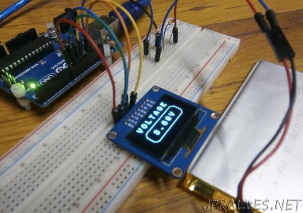
Measuring a DC voltage, should probably be as easy as connecting the voltage to be measured to an analog pin on the Arduino, but this becomes complicated when voltages are higher than the Arduino’s operational voltage (5V). When applied to an analog pin, Arduino will not only give a false reading but it could also damage the board. To solve this, today’s project uses the principle of voltage divider such that only a fraction of the voltage to be measured is applied to the Arduino. This fraction of voltage that goes in is determined by the ratio of the resistors used, as such, there is usually a limit to the maximum voltage that can be applied. For this tutorial, we will use a combo of a 100k and 10k resistor, with the 10k resistor on the “output side”. Feel free to experiment with other resistor values as well.To make the voltmeter fully functional, we will add a third part, which is an SH1106 controller-based, 1.3″ OLED display, to show the value of the voltage being measured by the voltmeter.It is important to note that this voltmeter can only monitor DC voltages within the range of 0-30v due to the values of the voltage divider used. It will require a voltage conversion circuit to be able to measure AC voltages.
Let’s dive in.”