
“The 555 Timer IC is one of those evergreen and versatile ICs that finds place in every common place electronics applications. What does it do? It generates a square wave used in timing applications and many other fields. It mainly has three modes of operation – monostable, abstable , bistable. Each of these modes can be implemented by using very few additional components.
Here, I will show how you can make your own version of the 555 timer using just NAND gates, opamps , a transistor and a few resistors! Now, you may think what is the purpose of building this when you can buy the IC at very cheap rates. The answer is, you learn electronics better, understand how the actual IC functions and improve your confidence in building electronic circuits. Let us first take a look at the simplified circuit diagram for our own 555 timer.
Observe that I have created a voltage divider configuration using three 4.7K Ohm resistors. The actual IC uses 5K Ohm (hence its name) but 4.7K Ohm was readily available to me. This network creates two voltage levels Vcc/3 and (2*Vcc)/3. Then there are two opamps that are being used as comparators here. The voltage levels connect to the individual opamp inputs. The Trigger and the Threshold pins connect to the other inputs of the two comparators and serve the same purpose as the original IC.
Below the opamps, are two NAND gates that are interfaced to form an SR Latch. The output from comparator 1 Sets the latch while comparator 2 output Resets the latch. The output of the latch Q is the output for our entire circuit. The complemented output Q’ drives an npn Bipolar Junction Transistor through a 220 Ohm resistor. This transistor is used to discharge the timing capacitor and its collector is the Discharge pin, similar to the actual IC. The reset and Control Voltage pins present in the 555 IC have been ignored here just for the sake of keeping the circuit simple.
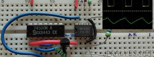
Now let us construct the actual circuit. We will use the 2-input Quad NAND Gate IC 74LS00 and an LM358 which comes as a dual opamp package. The 2N2222A transistor will be our BJT here. An astable multivibrator is implemented with this circuit using two resistors each 6.8K Ohm (taken arbitrarily) and a 60 nF capacitor.”