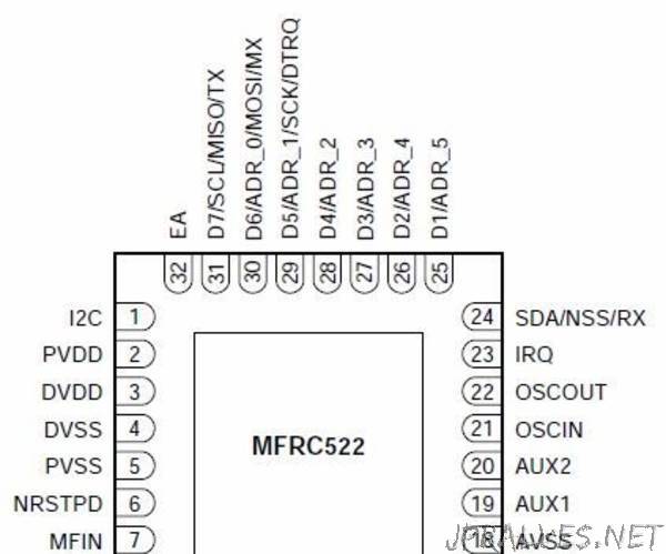
“Some time ago I bought three different RFID modules for experimenting. In a previous project I detailed how to use a simple 125-kHz module to do a basic security function. Modules like that use read-only tags so the process is scan for the ID, store if desired, and compare against stored IDs. The other modules I bought operate at 13.56-MHz and use tags that can be both read and written so its kind of a waste to simply use them for basic security. The two common modules use either the RC522 chip or the PN532 chip both made by NXP.
If youve read any of my other projects you know that I like to use cheap PIC microcontrollers and program in assembly language. So what I was looking for was a sequence of steps required to talk to the modules and to the RFID tags. While there are lots of example programs online for the modules, most of them are written in C software for the Arduino and use the SPI interface. Also, the manuals for the chips and for the Mifare tags take a bit of deciphering. This post is primarily about the information I wish I had when I started the project. I also include PIC assembly software programs for performing the basic commands required by each module. Even if you dont use a PIC and/or assembly language, the source code should at least provide you with a good idea of the specific commands required to perform each step.”
