“The serial port is a very commonly used interface for communicating between a microcontroller and a PC for debugging or sending or receiving some values. Most microcontrollers include a hardware peripheral called UART (Universal Asynchroneous Receiver Transmitter) which handles the serial communication, but some especially small microcontrollers (like the ATtiny24a that I am using) don’t have one.
In this case we can implement the communication in Software. This approach is often called bit bang’ing and can be used to emulate all sorts of communication peripherals. Another use case might be, that in an existing project the pins tied to the hardware-UART are already in use, in which case we could also use a software-UART. Since it is implemented in software, every GPIO pin can be used.
Now let’s take a quick look at how the serial communication works. As the name says, the communication is asynchroneous, but what does that mean?
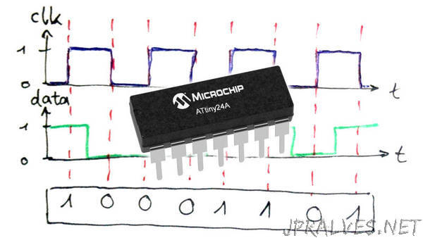
The opposite is a synchroneous communication protocol, which has a clock signal and one (or more) data signals. At every clock cycle, the receiver knows that there’s a new bit available and reads it. That way the clock frequency controls the rate at which data is being sent. In the below diagram we can see a clock signal (blue) and a data signal (green). “
