
“Introduction
SERCOM (Serial Communication) is a multiplexed serial configuration used on the SAMD21, SAMD51 and other boards. It allows you to select various serial functions for most of your pins. For example, the ATmega328 which has UART (RX/TX) on one pair of pins, I2C (SDA/SCL) on another set, and SPI (MOSI, MISO, SCK) on another set. The SAMD21 has 5 different internal ports which you can configure to use any combination of UART, I2C, and SPI. The SAMD21 and SAMD51 boards are becoming increasingly popular in part because of this feature. But how do you do it?
Required Materials
To follow along with this tutorial, you will need the following materials. You may not need everything though depending on what you have. Add it to your cart, read through the guide, and adjust the cart as necessary.
ARM-Based Microcontroller
For this tutorial we are going to use the RedBoard Turbo, but you should be able to follow along just fine with any of the SAMD21 boards below (or any not listed below).
A Look at the RedBoard Turbo
Whenever a new board is added to the Arduino IDE it comes with a couple of variants files (variant.h and variant.cpp). These files define which pins are being used for what. They define where D0 maps to, where the BUILT_IN_LED goes, and which pins are assigned to things like UART, I2C, etc. Pretty much any of the SAMD21 or SAMD51 boards you come across should already have at least 1 UART, I2C, and SPI port defined in their variants file. It is usually easiest to just use those. But once in a while you will want to add another port. For example you have an accelerometer that you want to use to measure vibrations on 2 different platforms. But the accelerometer only has one available I2C address. While you could use an I2C mux, you can also just add a second I2C port to your board.
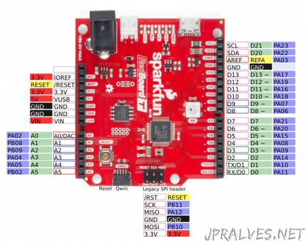
Let’s take a look at the Redboard Turbo. As you can see there is an I2C port broken out at the top right. Below that there is an SPI port. While it is not labeled the variant file does define those as SPI pins which are common at this location on an Arduino board (this is where the original board put the SPI port). At the bottom, you’ll also see the UART broken out and the pins labeled TX and RX. Finally, you’ll see what is often refered to as the legacy ISP header. Originally, this SPI port was tied to the one on the side of the board (the ATMega boards only had 1 SPI port) and was used to program the bootloader onto the board. Because a lot of shields use this as the primary SPI port this is broken out as well, but on the Redboard Turbo is on a different SPI port than the one on the side.”