
“This instructable is a follow up to the “ATtiny84/85 In-circuit Debugging with Serial Output” instructable and extends that hardware and software configuration to address the issue of reuse of the programming download pins by the application program. Altogether, between this and the part 1 instructable, the following topics are discussed/demonstrated:
TopicATtiny84ATtiny85Serial Communication using the SoftwareSerial classX X Sharing device pins between application and downloadX X Pin Change interruptXExternal interruptXSleep in POWER_DOWN mode; wake on interruptXWork-around for the “multiply defined” interrupt vector link error related to SoftwareSerialX In-circuit modify, download, debug, … development cycle for the ATtiny devicesX X Adding a hardware I/O component to one of the pins dedicated to the SPI programming interface is sometimes OK, sometimes not. For example, adding a LED to MISO just causes the LED to flicker during download and then it is available for the application. However, adding a piezo buzzer to MISO will result in a horrible screeching sound followed by download failure.
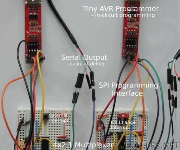
This instructable explains how to use a 4x2:1 multiplexer to “recover” use of the pins assigned to the SPI interface MISO, MOSI, and SCK signals by protecting them during download. Reuse of the RESET pin requires a fuse change and is not covered by this approach. Dual assignment of the pins is accomplished by using the multiplexer to switch between the application and programming inputs depending on whether download is in progress. Code and schematics are included for both the ATtiny84 and ATtiny85. The ATiny84 configuration is addressed first since it has two I/O ports and can be used to illustrate some additional problems/solutions. Following the tiny84 discussion, the same scenarios are discussed for the ATtiny85.”