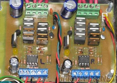
“This motor-driver is an H-bridge circuit that was designed to drive a single DC motor at up to 30amps at 24vdc. It incorporates a simple design utilizing parallel mosfets to allow a higher amperage rating and requires 4 wires to control each bridge, 2 digital and 2 PWM capable. You can find the files to build one here: https://sites.google.com/site/arduinorobotics/home/chapter8 The high-side switches in each bridge are high-power P-channel mosfets intended to be digitally controlled (On or Off) using a set of small n-channel signal transistors (2n7000). One signal transistor can supply up to 200mA of current to each set of P-channel mosfets to turm them On, while 2.2k pull-up resistors keep them turned off when not in use. While the schematic shows the signal transistors as 2n7000 n-channel mosfets, you can substitute these for standard 2n2222 BJT signal transistors as they will both fit. The low-side switches are high-power N-channel mosfets controlled by a PWM signal from a microcontroller which is passed through a mosfet driver IC (TC4427) to buffer the signals making ultrasonic PWM frequencies possible (32kHz tested). The low-side switches have gate resistors to ensure even current levels to each mosfet from the driver IC, and shottkey diodes at each gate to close the mosfet more quickly, which will allow for higher switching speeds. Each signal input is grounded thorugh a pull-down resistor to ensure that all switches are turned off when not controlled by the microcontroller.”
