
A Logical Analyzer is an electronic test equipment that captures and displays the activity of digital signals over a period of time. Typically this activity is presented in the form of a voltage versus time graph and is used to determine if the circuit design is working correctly. A logic analyzer displays the signals as logic values at 1 (HIGH) or 0 (LOW).
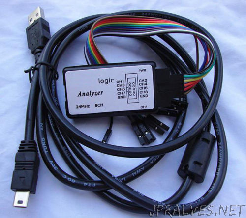
The analyzed Gadget allows capture of simultaneous information on 8 channels with speeds of sampling up to 24 MHz. It is a Chinese clone of Saleae Logic that uses a Cypress CY7C68013-56PVC. Connects to PC via USB cable.
There are several applications that can interact with this Gadget. We will see the operation with two of them:
These applications are run on a PC. The 64-bit Linux version was tested.
The Saleae application has more features, but is nevertheless closed-source.
For this to work without having to run in root mode the ‘install_driver’ script of the ‘Drivers’ folder must be run.
This step must be done without the gadget connected. After this procedure you will be able to execute the program without root privileges.
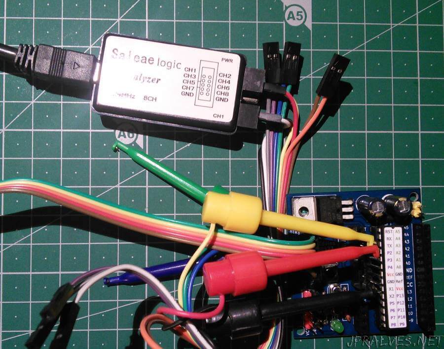
The way this Gadget works is relatively simple. There are 8 pins that can be connected with probes to the circuit. It must be ensured that the GND is also connected to the GND of the circuit.
Test
An information capture test was performed in a serial communication between CSEduino and the PC at the time of flash programming.
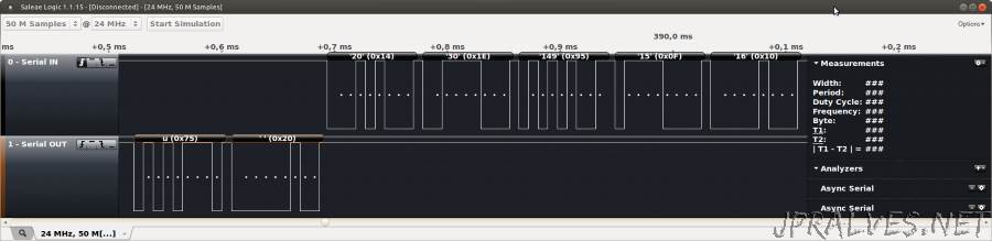
In screen capture you can see the command ‘u’ (0x75) which is given the 0x14 response followed by the chip ID: 0x1E 0x95 0x0F which corresponds to the ATMega328P. This is part of the STK500 protocol that is implemented in the Arduino optiboot.
To analyze the capture, two Analysers - Async Serial were defined, one for the RX pin and the other for the TX pin for the parser to decode the signaling.
Saleae Logic has more decoders in particular for:
- I2C
- SPI
- 1-Wire
- USB 1.1
- JTAG
- SWI
- Manchester
- CAN
- DMX512
- I2S
- UNI/O
In the application the number of “Samples” and the capture speed is defined - at most 24 MHz and if the capture starts immediately or only when there is a trigger on one of the pins being read.
The second application analyzed is the PulseView that is part of the package sigrok and from which the results were less satisfactory.
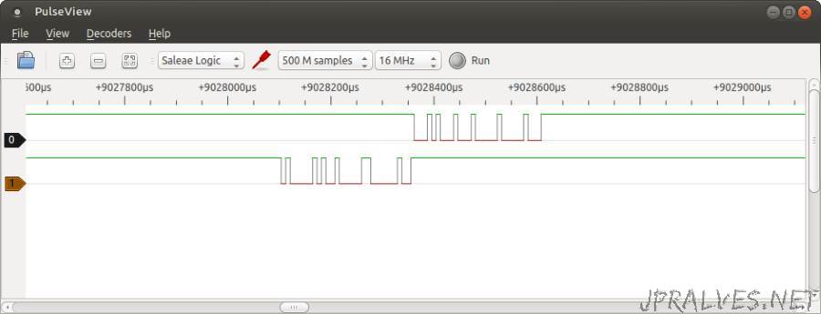
It was possible to configure the device and capture the signal variations but it was not possible to decode it.
Conclusion
It is a useful tool for debugging more complex protocols. By the cost associated with it we can say that does the job in a very simple way. It is an interesting tool to have in the toolbox.
Useful links: