
“In the EU country Latvia maximum permitted extinction coefficient k = 3 (1/m) at max motor revolutions 5000/min. Upon yearly check-ups my car frequently exceeds the limit value. Because I drive only in the city and soot deposits in catalitic converter. A cure is to drive outside the city for at least an hour so that catalytic converter heats up to > +300°C and soot burns in the presences of palladium catalyst.
Because I specialize in optical spectroscopy I became curious how the commercial measurement device AVL DiSmoke 280 works. Found a manufacturer data sheet. It has a lamp and photodetector on opposite ends of a L= 21.5 cm long tube. Why this length? It gives 1/2 of light absorption at k = 3. More exactly transmitted light has to be more than 53% to pass the exhaust cleanness requirement.
Beer-Lambert law of absorption in turbid medium:
Iexit / Iinitial = exp(-k L )
k = - ln( Iexit / Iinitial ) / L
where k is the extinction coefficient measured in 1/m and L is the absorption path length.
For example a 1 m long test tube at k = 3 would give a small transmission of only 5 % that is hard to measure precisely, so optimal tube length is where transmission drops to half.
I decided to build a device measuring diesel exhaust smoke. Searched the web and found on a Hackaday a link: https://www.rmcybernetics.com/science/diy-devices/diy-air-quality-meter. But in that prototype a general purpose air quality module measuring the scattered LED light saturated at diesel smoke levels. So I decided to take as a base prototype the DiSmoke commercial device. Used threaded water pipes to set optical distance of 21.5 cm between the two glass windows. On a diamond wheel cut two round glass windows to fit into the pipe and glued with 5 min epoxy. Pipes can be unscrewed for cleaning.
Light source is an Ebay LED torch with a collimating lens driven from a single AAA battery. Torch needs to warm up about one minute to stabilize the output intensity. Photodetector OPT101 has an integrated OP-amplifier supplied from +5V. Internal 1M feedback resistor is shunted by 200k (10-turn) variable resistor. This resistor allows to adjust the photodetector gain to full range when soot deposits on windows. I choose that 100% level is 500 Arduino ADC input units. Photodetector is separated from Arduino LCD box by a 3 m shielded cable (an old USB cable) so that driver can see the meter display sitting at the steering wheel. Red and black wires supply 5V to the photodetector amplifier. Green wire is photodetector output and white wire is from a variable feedback resistor. There was a worry that feedback resistor at 3 m separation would pick up noise but no problems were noticed as Arduino averages analog input reading 1000 times. Full screen is 500 Arduino ADC input units normed using map function to fill the display vertical 64 pixels . Made a moving marker on LCD marking 53%.
128x64 display from 3D printer bord was used displaying about 2 points per second. LCD in serial data mode uses Arduino pins D10, D11, D13. YouTube video about the display use with Arduino: https://youtu.be/ueMiQeVOCmo
It took me some time to figure out how to display numeric value together with graphics using sprint() function. As there is no storage implemented, I took display photos by a phone.
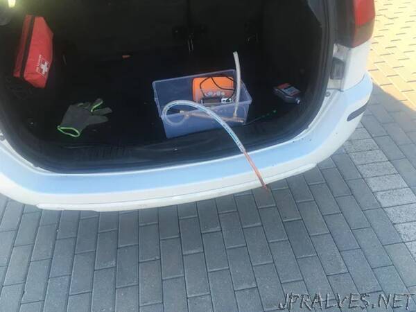
Device was supplied from three 18650 LiPos salvaged from an old PC soldered in parallel and charged by a powerbank circuit board from Ebay.
10 mm outer diameter soft copper pipe was put into exhaust linked with a plastic tube. It did not get too hot so could touch it with a bare hand. My prototype was assembled and tested in 2 days, and it took one more day to put it in a nice housing. Whole project can be stored in a shoebox till next year car inspection.”