
“In this project, a GreenPAK™ SLG46140V is used to create a Class-D Audio Amplifier
In this project, we will use a Dialog GreenPAK™ SLG46140V to create a Class-D Audio Amplifier. A Class-D amplifier takes an analog audio signal, converts it into a digital PWM signal, and then filters the PWM signal to recapture the analog signal with a greater amplitude for greater volume.
Below we described steps needed to understand how the solution has been programmed to design the audio amplifier. However, if you just want to get the result of programming, download GreenPAK software to view the already completed GreenPAK Design File. Plug the GreenPAK Development Kit to your computer and hit the program to design the solution.
Input and Output Signals
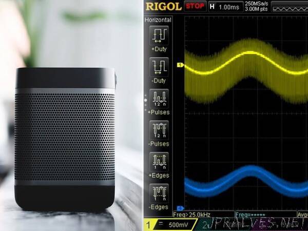
Figure 1 shows the input and output signals used in this project. The analog waves that come out of an iPhone headphone jack are centered around 0 v and have an amplitude of between 1-2 v. We need to process that analog signal through our GreenPAK’s ADC (analog to digital converter), but the GreenPAK ADC can only convert positive values from 50 mv to 1200 mv. This means that the first thing we need to do is add a 600 mv DC offset to the input signal. The amplitude of the input signal remains the same, but it is now centered around 600 mv as shown in Step 2 of Figure 1.
We can do that by adding a series capacitor and a resistive divider to our circuit, as shown in Step 2 of Figure 2. The voltage coming out of the GreenPAK’s Pin3 is 1.2 v, which means that the waveform that enters Pin6 will be centered around 0.6 v. We’ll discuss how to create that 1.2 v rail in the GreenPAK Design section.
The GreenPAK takes the voltage that it receives at Pin6 and converts it into several different PWM signals which are output on Pins 9-12. Those signals are used to control the gates of 4 MOSFETs which are configured as an H-Bridge. In order to maximize the voltage potential across the speaker, pFET0 and nFET1 are turned on at the same time, and pFET1 and nFET0 are turned on at the same time.
To recreate our analog input signal, we added a pair of LC filters to both sides of the H-Bridge. The outputs of both filters are connected to the speaker terminals.”