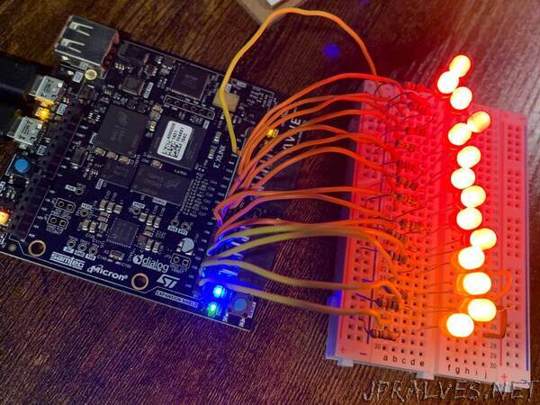
“Enable the digital I/O available on the Arduino shield header of the MiniZed.
While working on another project, I noticed that the hardware design in the BSP for the MiniZed has the pinout of the Arduino GPIO header specified in the Vivado constraints file (.xdc) but it doesn’t actually have them connected to anything in the hardware block design. I decided it would make a good standalone tutorial of how to enable the digital IO on the Arduino shield header as I haven’t seen a ton of other specific resources for it.
(Side Note: I am using Vivado/Vitis/PetaLinux 2019.2 for this project. I noticed while in the middle of this project that the Avnet Github repositories have updated quite a bit for version 2020.1, particularly for the MiniZed. So the exact steps for the Vitis aspect of this project and which files to upload to the MiniZed will be slightly different if you are using version Vivado/Vitis/PetaLinux 2020.1 or newer.)
I am starting with the Vivado and PetaLinux projects that I created from the MiniZed BSP in my last MiniZed project here. The first thing that needs to be done, is the updates to the hardware in Vivado.
To modify MiniZed based hardware design, open the Vivado project in the PetaLinux project directory generated by the BSP under the «project path»/hardware/MINIZED directory.
Since the EMIO GPIO of the Zynq are already being used for the bluetooth’s I/O, add an AXI GPIO to the block diagram. Before running the connection automation option that appears, double-click on the new AXI GPIO block to reconfigure its settings.
Configure the GPIO block to have a single channel 14 bits wide connected to a custom endpoint. Click ‘Ok’ to save and close the configuration window then run the connection automation from the green banner at the top of the block design. Again, be sure that the GPIO connection option is set to ‘Custom’.”
