
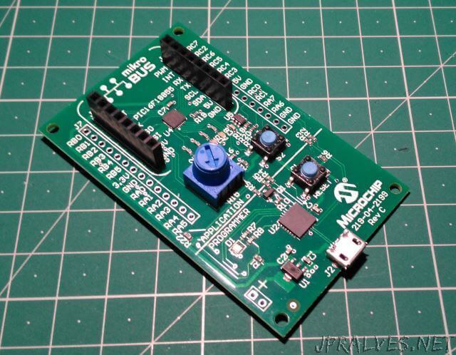
Today’s Gadget is a development board developed by Microchip designed to demonstrate the capabilities of the MPLAB Xpress Cloud-based IDE.
This board comes with an 8-bit PIC16F18855, one USB port, LEDs, one pushbutton and one potentiometer. The MCU pins can be accessed through headers on the board.
The Micro-controller has the following characteristics:
- VDD de 1.8 a 5.5 V
- 14 KBytes of Flash
- 1024 Bytes RAM
- 256 Bytes EEPROM
- Internal Oscillator adjustable between 1 and 32 MHz
- PWM de 10-bits (2)
- UART (1)
- SPI (2)
- I2C (2)
- Timers (5) - 4 timers of 16-bits and 1 of 8-bits
- ADC of 10-bits with 24 channels
- DAC of 5-bits
The board in addition to the microcontroller has the following components:
- A PIC18LF25K50 for the USB interface and for programming
- 4 red LEDs
- 1 Potentiometer
- 1 push-button
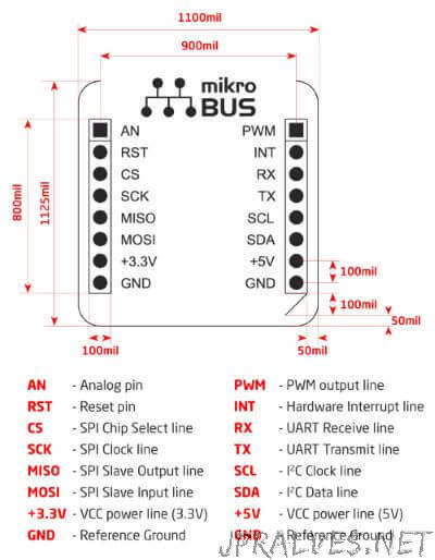
- header mikro BUS - Spec
The header has the following configuration:
When the card is connected either on Linux or Windows a new drive appears mapped. On this drive is a file - README.HTM that opens up takes us to the mplab-xpress site of Microchip. To reprogram the micro-controller, simply copy the .HEX file that is generated by the platform to this drive for the programming to be done.
After proceeding with the registration process on the platform, we can start programming.
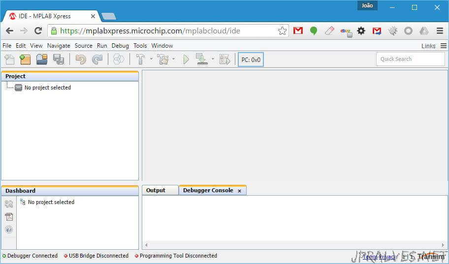
In this interface we will do the first test with this board.
Choose File -New Project - Microchip Examples -Hello World. Click on Next to choosePIC16F18855 on the Device. You can leave the default name - Hello_World. After these operations the project tree should already be populated.
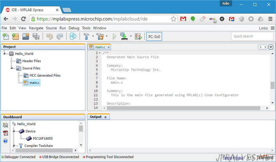
At this point we already have a project ready to be compiled and used. Press the Make and Program Device button. This will compile the program and download a .hex file. This file can be placed on the XPRESS drive. This will trigger the programming of PIC16F18855.
If all goes well we will have the PIC with the first LED lit (D2).
Now we will enter the MCC - MPLAB Xpress Code Configurator tool. Access this tool through the Tools menu -Embedded - MPLAB Xpress Code Configurator. At this point we need to have Java 8 installed and we should press the “Download MCC” button. It downloads or executes a jnlp file. If it is just downloaded it should be executed. Then the application will ask for a token. You should enter what is in Step 3. This will initialize the MCC which, after initialization, should look like this:
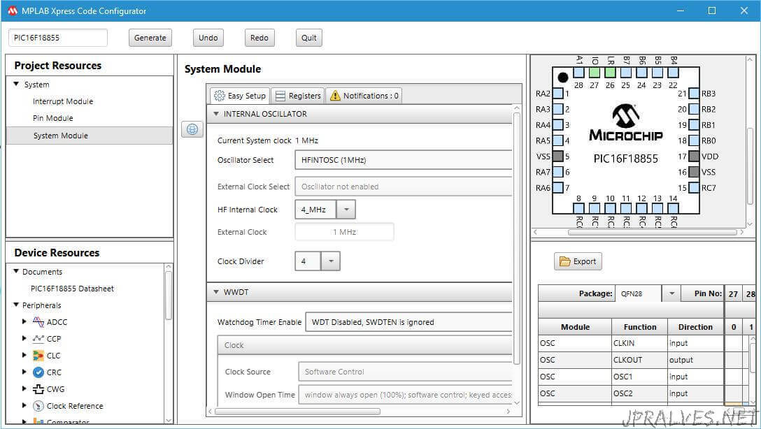
In this application (MCC) we will configure the pins of the micro-controller that we want to use. In our case we will use the following pins:
- RA0 - GPIO - led1 - Output
- RA1 - GPIO - led2 - Output
- RA2 - GPIO - led3 - Output
- RA3 - GPIO - led4 - Output
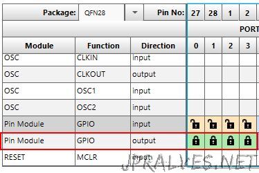
These settings are made at the bottom right of the MCC:
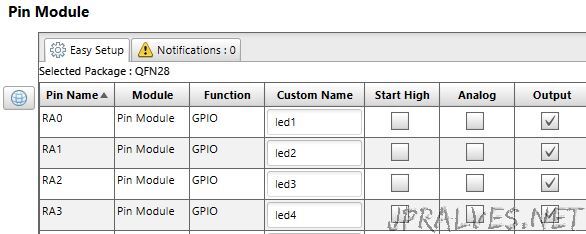
Then the pin mode and its logical name are configured:
After this configuration we can click on the Generate button of the MCC. Answer yes in “Warning”.
At this point the MCC tried to generate a set of primitives that can now be used in our application (ficheiro pin_manager.h):
#define led1_TRIS               TRISA0
#define led1_LAT                LATA0
#define led1_PORT               RA0
#define led1_WPU                WPUA0
#define led1_ANS                ANSA0
#define led1_SetHigh()    do { LATA0 = 1; } while(0)
#define led1_SetLow()   do { LATA0 = 0; } while(0)
#define led1_Toggle()   do { LATA0 = ~LATA0; } while(0)
#define led1_GetValue()         RA0
#define led1_SetDigitalInput()    do { TRISA0 = 1; } while(0)
#define led1_SetDigitalOutput()   do { TRISA0 = 0; } while(0)

#define led1_SetPullup()    do { WPUA0 = 1; } while(0)
#define led1_ResetPullup()   do { WPUA0 = 0; } while(0)
#define led1_SetAnalogMode()   do { ANSA0 = 1; } while(0)
#define led1_SetDigitalMode()   do { ANSA0 = 0; } while(0)
These are just the ones that were generated for led1.
At this point we can build our program. Opening main.c we should put insidewhile (1)the following:
    while (1)
    {
        #define  tempo 100
        led1_Toggle();
        __delay_ms(tempo);
        led2_Toggle();
        __delay_ms(tempo);
        led3_Toggle();
        __delay_ms(tempo);
        led4_Toggle();
        __delay_ms(tempo);
    }
Then we can compile the code and put the generated .hex in DriveXPRESS.
The effect will be to see leds turn on and off in sequence.
This is just a small example of what can be done with this board.
Conclusion
The programming made on this board is “similar” to what is done in a traditional IDE.
Not being an Arduino, it can also be an interesting option to better understand how microcontrollers work, in this case the PICs.