
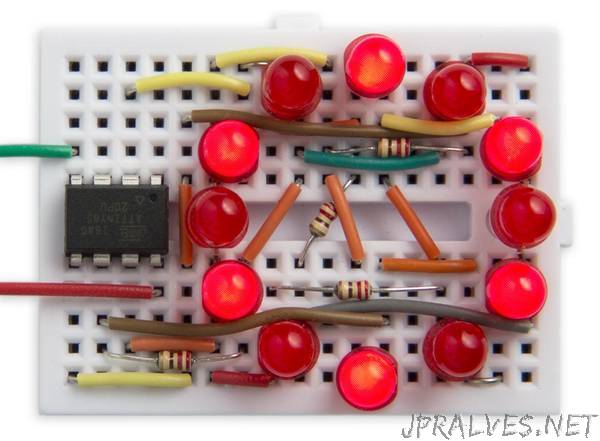
“This project describes how to get 12 analogue PWM outputs from an ATtiny85, so you can drive 12 LEDs with individual control over each LED’s brightness
Each LED can be set to a brightness between 0 (off) and 63 (fully on). The demonstration program shows a rotating wave of light that moves around the circle.
The circuit could be used for a range of applications, from interactive LED displays, jewellery, or controlling the lights in a dolls house. It leaves one free I/O line on the ATtiny85, so you could control the light display from a sensor, or serial input.
Introduction
The usual way of getting PWM outputs on the ATtiny and ATmega chips is to use the built-in hardware timers to generate a waveform output with an appropriate mark-space ratio. This is how the Arduino analogWrite() command works. The ATtiny85 and ATtiny84 only have two timers, each of which has two outputs, so the maximum number of PWM outputs you can get this way from either of these chips is four.
An alternative way of getting PWM outputs is to use one of the timers to generate an interrupt; then, in the interrupt service routine you toggle each of the outputs as appropriate for the mark-space ratios you want to output. This requires a bit more programming, but lets you have PWM on every output. In the case of the ATtiny84 this could give you 5 PWM outputs, and on the ATtiny84 it could give you 11 PWM outputs.
This project goes one step further. It uses charlieplexing to allow you to connect an LED between each pair of I/O lines and then lets you control the brightness of each LED with PWM.
Charlieplexing
Charlieplexing takes advantage of the fact that each I/O line can have one of three states: low, high, or high-impedance when defined as an input. All the I/O lines are defined as inputs when no LEDs are illuminated, and to light one LED you take one I/O line low and another I/O line high. The LED at the intersection of those two lines will then light up.”