
“Introduction:
Spent many head breaking hours just to get started with this tiny latest ESP8285 M3 board but unfortunately could not get even single link where all the information was present in one place. So thought of sharing this article with you all. Lets get started…
ESP8285 is a coin sized SoC(System on Chip) IoT(Internet of Things) capable board with very less power consumption(Deep Sleep option compatible).
In this article will be demonstrating how to upload basic Blink led code.
What is ESP8285?
ESP8285 = ESP8266 + 1M Flash, so that it can withstand high temperatures up to 125 degrees Celsius! And the original ESP8266 source code program can be used to transplant. ESP-M3 module core processor using cost-effective chip ESP8285. The chip integrates the enhanced version of the Tensilica’s L106 Diamond 32-bit core processor with on-chip SRAM in a smaller package. ESP8285 has a complete Wi-Fi network function, both can be used independently, can also be used as a slave from other host MCU running. When the ESP8285 hosting application, can be started directly from the external Flash. Built-in cache memory facilitates system performance and optimizes storage systems. In addition, ESP8285 only through the SPI / SDIO interface or I2C / UART port can be used as a Wi-Fi adapter, applied to any microcontroller-based design.
Chip Manufacturer link: https://www.espressif.com/en/products/hardware/esp8266ex/overview
Features
1) the volume is ultra-small; 2) serial to WiFi; 3) wireless transmission; 4) long-range ultra-low power consumption; 5) high temperature, up to 125 6) fully compatible with ESP8266, the source can be used to transplant.
SOC characteristicsBuilt-in Tensilica L106 ultra-low power 32-bit microprocessor,
clocked at 80MHz and 160MHz support RTOS Built-in TCP / IP protocol stack Built-in 1-channel 10-bit high-precision ADC Peripheral Interface HSPI,
UART, I2C, I2S, IR Remote Control, PWM, GPIO.
The deep sleep hold current is 10uA and the shutdown current is less than 5uA
Wake up within 2 ms, connect and pass the packet
Standby power consumption less than 1.0mW (DTIM3) Built-in 1M bytes of SPI Flash
Wi-Fi features
Supports 802.11 b / g / n / e / i
Support Station, SoftAP,
SoftAP + STA mode Support for Wi-Fi Direct (P2P)
Supports CCMP (CBC-MAC, counter mode), TKIP (MIC, RC4), WAPI (SMS4), WEP (RC4), CRC
Hardware acceleration P2P discovery, P2P GO mode / GC mode and
P2P power management WPA / PA2 PSK and WPS 802.11 i
security features: pre-authentication and TSN Hold 802.11n (2.4 GHz) 802.1h / RFC1042
frame encapsulation Seamless roaming support
Support AT remote upgrade and cloud OTA upgrade
Support for Smart Config features (including Android and iOS devices)
Module peripherals 2xUART 1xADC 1xEn 1x wakeup pin 1xHSPI 1xI2C 1xI2S Up to 10xGPIOs
Operating temperature range: -40 -125
How did I make my first application with this chip ? Below are the steps
Kindly Note(Important): ESP8255 accepts max 3.3 v NOT 5v.
Software Needed:
1. FTDI board drivers based on type of FTDI board used
Hardware Needed:
ESP8285 Board: ESP8285-ESP-M3FTDI Cable: FTDI board with connection cableOn/Off Switch 2 AA battery and holderPre-Requisites:
1. Arduino IDE Setup and Config for ESP8285 board
https://randomnerdtutorials.com/how-to-install-esp…
Recommend to install version 1.8.3 or higher Arduino IDE
Note: After completing above step you should be able to see “Generic ESP8285 Module”.
Refer attached images.
2. Understanding ESP8285 board pin outs and mapping
Refer attached images.
More information(ESP8255 Data sheet): esp8285 datasheet
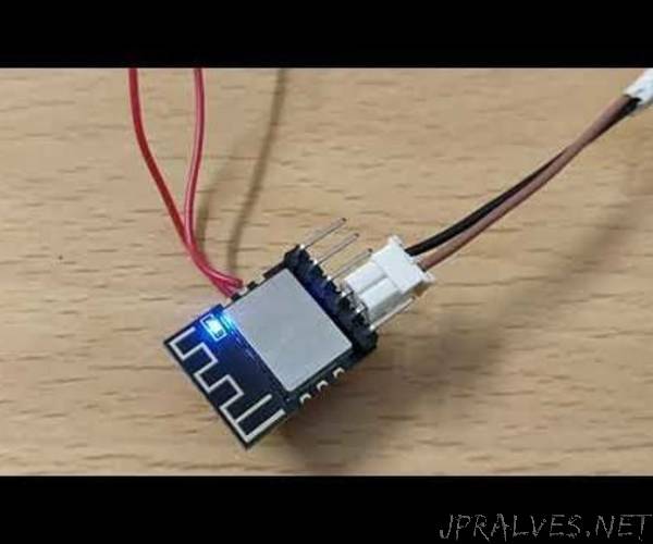
3. Hardware Setup before flashing/upload sample code from Arduino IDE
FTDI to ESP8285 board connection.
FTDI Pin ESP8285 Pin
——————- —————————-
3.3v VCC
Gnd GND
Rx Tx
Tx Rx
If Flash mode/uploading code: Then ESP8285 IO0 and ESP8285 Gnd have to be connected to each other else don’t connect(like post code upload). Refer images attached using a on/off switch to on and off flash and operational mode. Once use case is finalized one can de-solder this switch.
GPIO 0 i.e IO0 and Gnd of ESP8285 has to be shorted/connected before FTDI is in powered up. This tells the board to in flash mode or upload code to chip. Select Tools -> Board -> Generic 8285 Board Upload any ESP8266 compatable code. Once you see “Upload Complete” status in Arduino IDE means success and you can proceed to next step. Else make sure connection are made as per above steps. Disconnect GPIO 0 and Gnd. Now re power board(I use 2 x 1.5v AA regular battery) connect LED or any output to pin the code uploaded needs. If you don’t have any LED GPIO2 points to onboard blue led. You can upload blink.ino and make sure to trigger pin 2.4. Test Run
Now the default on board blue color tiny led should start blinking at an set interval of 1 sec gap.
5. Next Steps / Application scenario:
Household appliances Home automation Smart socket, smart light Mesh network Baby monitor IP camera sensor network can wear electronic products Security ID tag Wireless location awareness Wireless positioning system beacon Industrial wireless control
6. Live Demo: https://youtu.be/aYr0ok1M3Ps
Please refer to Arduino IDE compatible code(Blink.ino) and various images attached for easy reference.
What Next: Will share how to control devices/home automation using this wonderful, small yet very powerful chip.”