
“The most common 7-segment application is making the digital clock.
There are various commercial 7-segment parts available but their size is not big enough to make a wall mount type of digital clock.
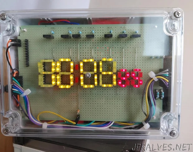
Thats why Im using the small square shape of LEDs for making big size and customized 7-segment-based digital clock.
Every day in the morning, frequently I need to check the clock to catch the company commuter bus going to my office. (About 45Km from my home)
Therefore, the digital clock is quite a useful device among the all DIY results from my all previous projects.
This is the first useful digital clock that supports the reliable and sustained operation.
Maybe several variants or possible upgrades can be possible later starting with this prototype.
Lets look at the details of this digital clock.
Although the schematics seem a little bit complex (frankly speaking it’s truly complicated while wiring and soldering this circuit), overall circuitry can be divided into four parts like below.
- DS3231 Real Time Clock (It’s the main component that keeps exact time data)
- Arduino Uno board for displaying the number on the LED 7-segment display
- LED-based 7-segment display showing time
- LM2596-based switching power supply module
As the DS3231 and Arduino Uno is quite common system boards, they will not necessary further explanation.
For this project, the Arduino Uno is used as it can supply significant current (more than 100mA) to peripherals.
Otherwise, the main controller (Arduino board) will be stressed so much and can’t support sustained operation in a 7x24 manner.
For the LED 7-segment display, a total of 7 transistors (BD140 PNP) are used for controlling 2 hours digit LEDs, 1 colon (Separator between hours and minutes with 2 LEDs), 2 minutes LEDs, and 2 seconds digit LEDs.
For every single 7-segment, a common anode type LED configuration is used to show a single numeric digit.
Utilizing a PNP transistor and common anode 7-segment display is a typical LED display module driving method.
I’ll explain how the time string (HH:MM:SS) is displayed on the 6 digits of 7-segment displays while explaining the sketch program at a later step.
As long and sustained operation is required as 7x24 by this digital clock, less heat producing and efficient LM2596-based switching power supply circuit is utilized instead of LM7805 voltage regulator circuit.
Usually, serial voltage regulator circuits (LM7805) produce quite much heat when the input voltage is quite high such as 15~18V.
Shown LM2596 circuit can support 15~18V input and produce 1.2 ~ 17V adjustable up to 3A power output.
Although a commercial LM2596 step-down voltage regulator breakout board is available, I tried to make a more reliable and sustainable power supply by making my own.
Therefore, more high-quality electrolytic capacitors and a bigger heat sink are used in my power supply circuit.
For making this digital clock, selecting a good equipment enclosure and a well-fitted size universal PCB was very important.
To use it frequently and conveniently in everyday life, good looking, dust protecting, and well-made equipment enclosure is highly desirable.
Therefore, the following parts are searched and purchased from the Internet shop.
- Plastic enclosure: Multicomp MC001108, 171mm(W)x121mm(D)x55mm(H)
- Universal PCB: 150mm(W) x 100mm(D), hole size 0.9mm and 2.54mm pitch (Between holes)
I’m always using acrylic boards for making equipment chassis (Usually air-tight enclosure is not possible with acrylic boards) to mount all circuit boards.
But making dust-protecting equipment box or enclosure with acrylic boards are not easy.
Therefore, I used commercially available and ready-made plastic enclosures.
Also finding the correct size of universal PCB board tightly fitting to the selected plastic enclosure is a little bit difficult.
Although I need to cut four corners of the universal PCB, luckily found PCB fitted exactly inside of the plastic enclosure.
For making a numeric pattern with square type of LEDs, an IC pin-header socket is used for plugging the lead of individual LED into it.
When you make an LED display PCB board like this, you can plug in other colors of LEDs later.
For making 6 digits of a 7-segment LED display board, the following parts are necessary.
- Yellow color square shape LED 56EA for HH:MM data displaying
- Red color LEDs 14EA for displaying seconds
- IC pin header sockets
- Male pin header for connecting transistor control and 7 data lines (a, b, c, d, e, f, g part of 7-segment pins)
- BD140 PNP transistors
- 1.5K resistors 6EA for driving BD140 transistors
- 150ohm resistors 6EA and 330ohm resistor 2EA (LED current limiting resistors)
Although I used a relatively heavy-duty transistor (BD14), you can use small signal general purpose PNP transistors such as 2N3906 or 2N4403.
Somehow I have numerous BD140s in my inventory and that’s why I used that transistor model.
As big size of 7-segment display parts (HH:MM) using two LEDs for 7 data segments (a, b, c, d, e, f, g), a small value (150ohm) of current limiting resistor is used for turn on LEDs more brightly.
But only 2 LEDs are connected for the colon (Separator between hours and minutes LEDs) part 330ohm current limiting resistor is used.
From the start, I considered putting a small size 5V cooling FAN inside the enclosure.
But controlling FAN with the sketch program and wiring the FAN control board becomes a little bit difficult.
Therefore, I discarded cooling FAN circuit parts from this prototype. (Maybe a later version will have it!)
For the LM2596 switch power supply circuit, the following parts are used.
- LM2596 adjustable switch power supply IC
- IN5822 SCHOTTKY BARRIER diode
- 33uH inductor (more than 3A)
- 220uF x 2 electrolytic capacitor, 0.1uF x 2 ceramic capacitor, 0.003uF film capacitor
- 510ohm, 680ohm resistors
- Power socket (male and female)
I’ll show details of the LM2596 switch power supply circuit in the later step.
Except explained parts mentioned above, the following common system boards are used.
- Arduino Uno compatible board
- DS3231 real-time clock breakout board
For connecting system boards and LED display/power supply PCB, DuPont wires are used.
Let’s look at each major PCB from the next step.”