
“The nRF24L01 is a common radio transceiver used with Arduino microcontrollers. They can be used for wireless communication, wireless data transfer, networks of wireless devices and remote-controlled robots. For a great tutorial on how to use them, I suggest the DroneBot Workshop tutorial (click here), which also has a YouTube video. The transceiver module uses the Serial Peripheral Interface (SPI) which is a convenient method for data transfer between electrical components wired together. There are some caveats to using the nRF24L01 transceiver however.
They are powered with 3.3 volts, rather than the 5 volts that most Arduinos typically use.
They require sudden spikes in current demand which can exceed what the Arduino board can supply in such a short period of time.
The layout of the pins is two rows of four pins which means it cannot be connected directly to an Arduino or even be used on a solderless breadboard.
Furthermore, because they are radio frequency receivers, they are best connected to the Arduino as close as possible to help reduce interference in the signal.
There are already inexpensive adapters that make the use of the nRF24L01 much easier. Just do a Google image search of “nRF24L01 adapter”. Typically, these have a voltage regulator so powering the device with a 5-volt supply will not damage it. Plus, the capacitors on the adapter accommodate the spikes in the current demand, and improve the reliability of the signals. However, the male pins on the adapter are usually on the top surface which again, prevents the adapter from being connected directly to the Arduino or a breadboard. And, this is personal preference, I don’t like how the transceiver has to “hang” off the back of the adapter, like someone wearing a baseball cap upside-down and backwards.
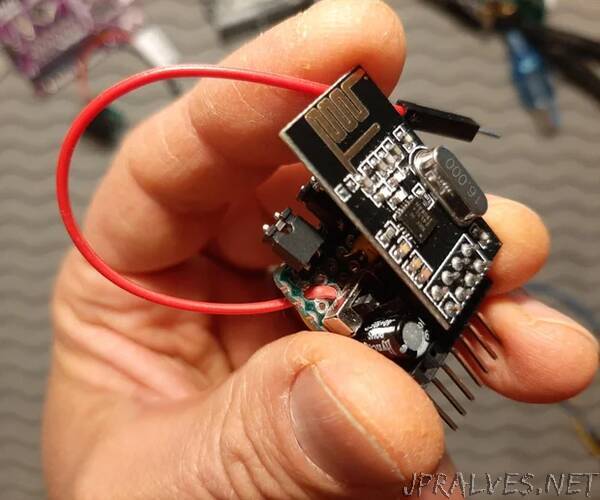
For all these reasons, in this Instructable I will show how I soldered together a DYI nRF24L01 adapter which attempts to solve a lot of these issues. This is not a beginner project, as you will have to solder the components together, but is otherwise rather simple. I think you will see; this adapter is easier to use than the commercially available one because it can be connected directly to an Arduino, or other microcontrollers that have the same pin layout, Arduino Mega comes to mind. It is convenient to use with a breadboard. It also has a capacitor for sudden increases in current demand, and an optional voltage regulator to manage electrical requirements. The pin layout is set up to work with the default setup of the RadioHead library (click here), which is open source so it can be downloaded for free. I tried to make the adapter compact, yet as versatile as possible, so it will work with multiple library codes for Arduino, can allow changes to some of the pins, and will work other devices that use the SPI communication. You will, of course, need at least two adapters because it takes at least two nRF24L01 to be able to talk to each other.
Supplies:
Parts for a single adapter:
nRF24L01 (or nRF24L01+) wireless transcevier
Arduino (UNO, Mega, or Nano, etc
Female header pins – enough for two 4-pin segments, and one 7 pin segment
90-degree male header pins – enough for one 7 pin segment, two 2 pin segments and a single pin
Jumper connectors x2
Perf board (2 x 2.5 cm)
Red jumper wire with a male pin end (~10cm)
Electrolytic capacitor 10-100 microfarad (uF)
Wire (I used 26 AWG)
Self-adhesive label - to remind you not to connect to 5V if you don’t have the voltage regulator
Soldering iron and solder
Optional parts for voltage regulator:
AMS 1117 3.3volt regulator
10 uF capacitor to use with the voltage regulator
Switch (single pole, double throw)”