
“Features
Constant Current, Power and Resistance modes
Battery capacity logging with adjustable cutoff voltage
Input and output power logging : instant efficiency reading for DC-DC converters
Rotary encoder driven interface
Dedicated Load ON/OFF button
Intuitive LCD menu system with editable values
12bit current, voltage and power measurements
30W continuous sinking capability, 250W peak
Temperature controlled fan with auto shutdown.
Adjustable acquistion rate
115200 bauds serial communication through USB with a PC (non-isolated !)
Specifications
Enough talk, give us the specs, son !
Altough the device has not been fully qualified through systematic testing, here are the basic specs you can expect.
Input voltage range : 0 - 100V DC maximum, 2-80V DC regulating
Supply voltage range : 0 - 16V maximum, 12V nominal
Device current consumption : 50mA nominal (0.6W)
Load current range : 5mA - 5.25A, in 8mA steps
Current regulation : 5% +/- 8mA typical @ 8kHz bandwidth
Transient response : rise time < 20µs/A, overshoot < 2%
Constant Power/Resistance regulation bandwidth : 10Hz
Schematic and Layout
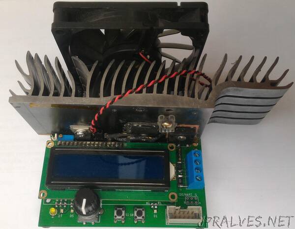
The heart of the system is an Atmel ATmega328P AVR microcontroller with 32kB of Flash and 2k of RAM running at a whopping 16MHz. It interfaces an I2C 12bit DAC (the MCP47FEB21A1) and the LTC2992 dual power monitor chip.
The USB serial interface uses the MCP2221A bridge. The display is a classic 16x2 LCD.
On the analog part, 10mΩ and 0.2Ω shunt resistors are used, coupled with two W9NK90Z N-ch power MOSFETS. The heatsink was salvaged from an old graphics card. Attached are a 10k NTC and a generic fan (12v @ 200mA, 80mm). Current regulation is achieved through the help of a MCP6H02 opamp, and a carefully designed feedback network which guarantees the specified rise time with little to no overshoot.
The layout was done using the Eagle software (v9.5.2). Gerbers, Eagle project files, top and bottom views are available on the pcb folder. PCBs were printed using JLCPCB service. The schematic is available in a pdf and Eagle .sch format as well.
Several user-definable bi-color status LEDs are included, such as Load ON/OFF, TX & RX, acquisition blink, as well as a power LED.
An expansion/debug port is provided, with +5V, ground, I2C and UART available.
There are several issues regarding the layout of the PCB, as it is a first version. Improper Kelvin connections to the current sense resistors, or wrong hole size for the power input connector by example. The heatsink originally used is salvaged from old equipement and the footprint may not be relevant to anyone else. Space for rubber feet placement should be included. Also, the LCD is too close to the heatsink, which is impractical during assembly (especially accessing the fan and temp sensor connector).”