
“Have you ever found 7-segment display multiplexing a little confusing? I created this project as a simple educational tool for explaining how multiplexed displays are driven and also as a super simple reference design for users who wish to integrate such a display into their project.
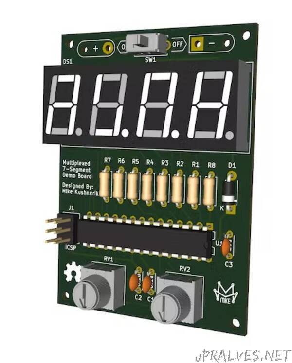
The device is comprised of an ATMEGA328P AVR microcontroller, common cathode, 4 digit, 7 segment display, and two potentiometers that are used to adjust the digital value shown on the display and the delay used in between driving each display digit. Everything is powered via two AA batteries enclosed in a plastic holder taped to the back of the board.
To prop the PCB up at a nice angle for viewing, I also designed some 3D printable legs in FreeCAD.
Software
Instead of the obvious choice of using Arduino for this project, I decided to try out Microchip/Atmel Studio and the Atmel ICE programmer. I quickly got accustomed to the new IDE and was able to get everything up and running pretty quickly.
The software is super simple and primarily consists of a loop to read the ADC channels connected to the two onboard potentiometers and update the digital value on the display (left pot) and a variable used to control the delay between driving each digit (right pot). Be sure to checkout the Git repo for full Atmel Studio project and source code!
Conclusion
Overall, this was a really fun project and hopefully it helps new makers/engineers with learning about driving multiplexed displays!”