
“The robot imitates a vehicle on the highway through changing lanes, producing a honking noise, and avoiding obstacles with infrared sensors.
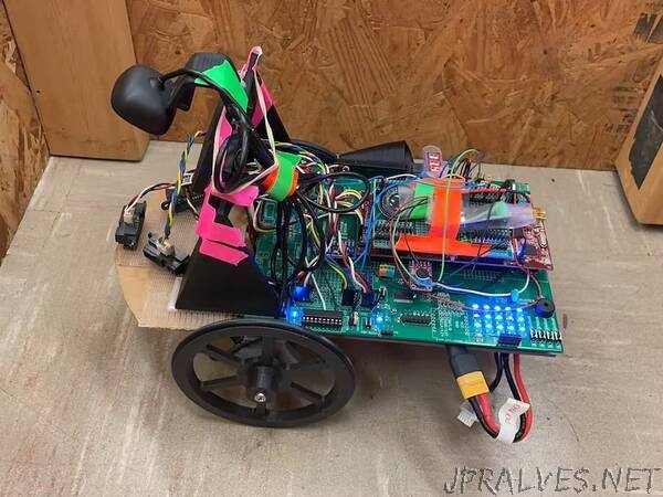
The team built a robot base from ME461. The project is based off the two-wheeled robot with a caster. The three-wheel robot is controlled by a TI launchpad F28379D. Besides, the three-wheel robot also contains a microphone, two wheel optical encoders and a 10 DOF IMU. To make the robot car capable of doing more intensive computation and communication, the team decided to add a Raspberry Pi 4 on it. A USB camera compatible with the Raspberry Pi 4 was mounted on the robot car for visual perception abilities. To perform obstacle avoidance function, the robot car is equipped with three range-finders on the front, left and right side. The team initially planned to have three ultrasonic sensors on each side, but was informed that multiple ultrasonic sensors might not work well due to noise and interference. As such, the team proceeded to substitute the ultrasonic sensors with three infrared distance sensors. The team also added a TI mini-speaker to output different horn sounds at designated intervals associated with obstacle avoidance. The horn consists of different sets of sound inputs that can be played during obstacle avoidance states using command input in the code.
The robot was put in a series of states. Each state serves a designated robot operation command, such as the “straight line routing” mode, which is the default operating mode, the “wall riding” mode when the front infrared distance sensor detects obstacles and commands the robot to go around them. There will also be several intermediate states between the line following and wall riding. For example, the vehicle will determine to use either right-wall or left-wall following depending on the location of the dash line. If the dash line is on the left, left-lane switching is allowed; similar to a real-life scenario, a left-wall following decision will be made. The states will be organized in a finite state machine so that the robot will transit among each state based on the sensor readings and camera images. A USB camera is used to locate different lines on the “high way” designed by the team. The differentiation between each line will serve to initiate the direction of wall-following. The vehicle utilizes a camera connected to Raspberry Pi 4 to do the visual recognition of the lines around the robot. An OpenCV-based algorithm was developed to detect if the lines are solid or dashed, which will determine the legal states of the robot (lane switch possible/impossible). For example, if the lines on both sides are solid, then wall-riding mode is illegal. If the left line is dashed, then the left-wall-riding mode is allowed.”