
“A small, simple and low-cost water flow meter is designed, built and tested using a Programmable Mixed-signal Matrix.
Introduction
An accurate, small, and low-cost liquid flow meter can be easily made using GreenPAK components. In this application note we present a water flow meter that continuously measures the water flow and displays it on three 7-segment displays. The flow sensor measurement range is from 1 to 30 liters per minute. The output of the sensor is a digital PWM signal with a frequency proportional to the water flow rate. Three GreenPAK Programmable Mixed-Signal Matrix SLG46533 ASICs count the number of pulses within a base time T. This base time is calculated such that the number of pulses is equal to the flow rate in that period, then this calculated number is displayed on the 7-segment displays. The resolution is 0.1 liters/min. The output of the sensor is connected to a digital input with Schmitt trigger of a first Mixed-signal Matrix that counts the fractional number. The chips are cascaded together via a digital output, which is connected to a digital input of a proceeding Mixed-signal Matrix. Each device is connected to a 7- segment common cathode display through 7 outputs. Using a GreenPAK Programmable Mixed-signal Matrix is preferable to many other solutions such as microcontrollers and discrete components. Compared to a microcontroller, a GreenPAK is lower cost, smaller, and easier to program. Compared to a discrete logic integrated circuits design, it is also lower cost, easier to build, and smaller. To make this solution commercially viable, the system must be as small as possible and be enclosed inside a waterproof, hard enclosure to be resistant to water, dust, steam, and other factors so that it may operate in various conditions. To test the design a simple PCB was built. The GreenPAK devices are plugged on this PCB using 20 pins double rows female header connectors. Tests are made first time using pulses generated by an Arduino and in a second time water flow rate of a home water source was measured. The system has shown an accuracy of 99%.
The complete design file is available here. It was created in the GreenPAK Designer software, a part of the Go Configure™ Software Hub.
Overall Description of the System
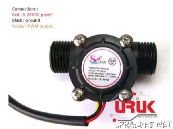
One of the most common ways to measure liquid flow rate is exactly like the principle of measuring the speed of wind by an anemometer: the speed of wind is proportional to the rotation speed of the anemometer. The main part of this type of flow sensor is a sort of a pinwheel, whose speed is proportional to the liquid flow rate passing through it. We used the water flow sensor YF-S201 from the firm URUK shown in Figure 1. In this sensor, a Hall Effect sensor mounted on the pinwheel outputs a pulse with every revolution. The output signal frequency is given by the relation: 𝑓𝑂𝑈𝑇 = 7.5 × 𝑄, where Q is water flow rate in liters/minute.
For example, if the measured flow rate is 1 liter/minute the output signal frequency is 7.5 Hz. In order to display the real value of the flow in the format 1.0 liter/minute, we have to count pulses for a time of 1.333 seconds. In the 1.0 liter/minute example, the counted result will be 10, which will be displayed as 01.0 on the seven-segment displays. Two tasks are addressed in this application: the first is counting pulses and the second is displaying the number when counting task is complete. Each task lasts 1.333 seconds.
GreenPAK Designer Implementation
The SLG46533 has many versatile combination function macrocells and they can be configured as Look up Tables, counters or D-Flip-Flops. This modularity is what makes GreenPAK suitable for the application. The program has 3 stages: stage (1) generates a periodic digital signal to switch between the 2 tasks of the system, stage (2) counts flow sensor pulses and stage (3) displays the fractional number.
Stage 1: Counting/Displaying Switching
A digital output “COUNT/DISP-OUT” that changes the state between high and low every 1.333 seconds is required. When high, the system counts pulses and when low it displays the counted result. This can be achieved using DFF0, CNT1 and OSC0 wired like shown in Figure 2. The frequency of OSC0 is 25 kHz. CNT1/DLY1/FSM1 is configured as a counter, and its clock input is connected to CLK/4 so that CNT1’s input clock frequency is 6.25 kHz. For the first clock period that lasts: 1 6.25 𝑘𝐻𝑧 = 160 µ𝑠, CNT1 output is high and from the next clock’s signal rising edge, counter output is low and CNT1 starts decrementing from 8332. When CNT1 data reaches 0, a new pulse on CNT1 output is generated. On each rising edge of CNT1 output, DFF0 output changes the state, if low it switches to high and vice versa.”