
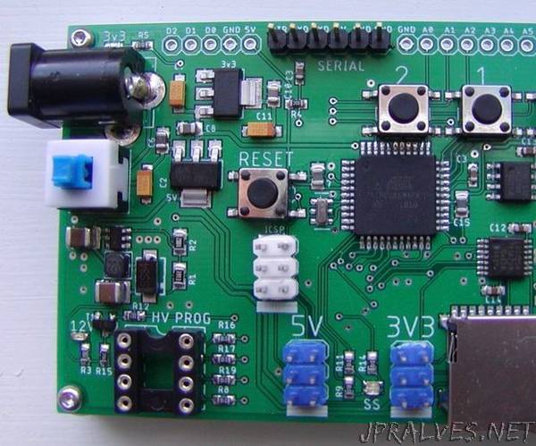
“This is my first Instructable. Using Eagle, the board I designed is an AVR Programmer. The board combines the functions of 4 separate prototype boards I’ve built in the last few years:
- A High Voltage AVR programmer, primarily used on ATtiny devices to set fuses when the reset line is used for I/O.
- Arduino as ISP, 5V and 3v3 (counts as two of the functions)
- NOR Flash EEPROM programmer (quickly copies from an SD card to NOR Flash)
The board uses common AMS1117 LDO voltage regulators to get 5V and 3v3. The high voltage function requires 12V. For this I used a MT3608 DC-DC step-up converter. The mcu runs at 16MHz, 5V. Level shifting for anything requiring 3v3 is accomplished using a LVC125A. The LVC125A is what you find on a lot of the SD card modules. I like the LVC125A because it comes in the tiny TSSOP package. I made two versions of the board, one uses an ATMega328pb, and the other an ATMega644pa. The ATMega328pb is nearly the same as the more common ATMega328p except that it has 4 more I/O pins in the same size package. The ATMega328pb is actually cheaper. I’m not sure why. If you read the spec sheet you’ll see that it’s a lot more useful. The only reason for the ATMega644pa version is that I wanted an excuse to play with this mcu.
The board lacks a usb serial interface. I’ve been using Arduino Pro Mini’s for so long with an external usb serial module that I didn’t really think of it till later. It would have been a nice addition. The board has the option of adding an AT24Cxxx I2C serial EEPROM and there’s a 5 pin I2C JST-XH-05 connector (GND/5V/SCL/SDA/INT1) for adding a display and/or other I2C devices. For both board versions I brought all of the unused pins to the edge so the board could be repurposed if needed. The reason for the serial EEPROM is that I’ve been using these chips to store bitmap fonts. I wrote an app that leverages FreeType to create bitmap subset fonts for use with Arduino displays (this app also will generate the bitmaps to support the rotated Nokia format). At some point I’ll publish it on GitHub.
As boards go, it’s quite simple. The somewhat more complicated part of this project was how to load all of the functions/sketches onto the board. The easiest method would have been to simply download a sketch whenever I needed to change functions. Another method would have been to combine all of the sketches. I decided against both of these methods. The combine method would have made it difficult to integrate any changes made to the original source sketches. The combine method also has the problem that the amount of SRAM available wasn’t sufficient without rewriting and digging into the libraries and sketches used, again a maintenance issue.
The method I chose was to write an application named AVRMultiSketch that works with the Arduino IDE to load the sketches into flash by shifting their memory locations. The sketch sources aren’t modified in any way. They run on the board as if they’re the only sketch. How this works is described in detail on the open source GitHub readme for AVRMultiSketch. See https://github.com/JonMackey/AVRMultiSketch for more details. This repository also contains the sketches I used/wrote/modified, which can be used individually.
To switch between sketches the board has four buttons: Reset, and buttons labeled 0,1,2. On power-up or reset, if you do nothing the last function selected is run. If you hold down one of the numbered buttons you’re selecting a sketch/function. The sketch becomes the selected sketch. Currently the board only hosts 3 sketches, but it could host a few more. In that case, assuming only 3 bits/numbered buttons, it could host up to 7 by holding down more than one button.”