
![]()
Today I am going to talk about Espruino Pico. Espruino Pico is the evolution of Espruino in a USB format. The Kickstarter campaign is over and I already got the gadget.
Created by Gordon Williams this gadget allows one to make programs in JavaScript for controlling pins of the board.
This gadget cost me £ 17.
What is Espruino Pico?
It is a small board with a microcontroller that runs a JavaScript interpreter allowing easy control of electronic components through I/O pins.
It has everything you need pre-installed. It can be used virtually from any device that has a USB port. In the case of Windows requires installation of drivers (see below)
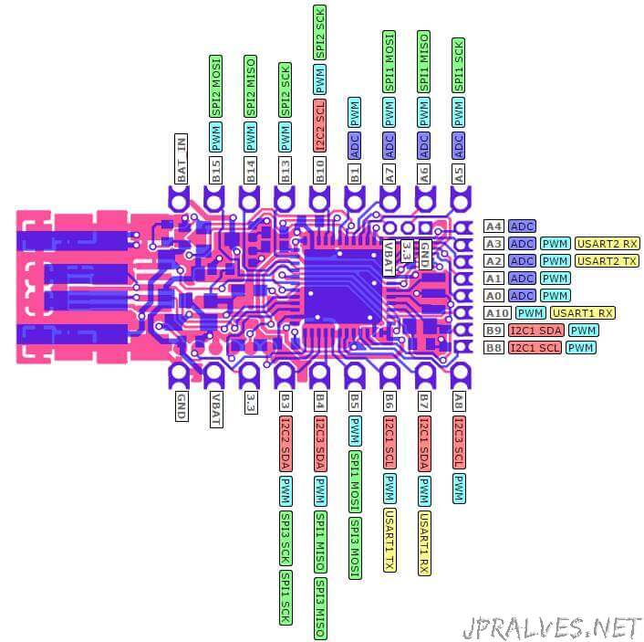
- Purple boxes show pins that are used for other functionality on the board. You should avoid using these unless you know that the marked device is not used.
- ! boxes contain extra information about the pin. Hover your mouse over them to see it.
- 3.3v boxes mark pins that are not 5v tolerant (they only take inputs from 0 - 3.3v, not 0 - 5v).
- 3.3 is a 3.3v output from the on-board Voltage regulator.
- GND is ground (0v).
- VBAT is the battery voltage output (see the Espruino Board Reference).
- ADC is an Analog to Digital Converter (for reading analog voltages)
- PWM is for Pulse Width Modulation. This creates analog voltages from a digital output by sending a series of pulses.
- SPI is the 3 wire Serial Peripheral Interface.
- USART is a 2 wire peripheral for Serial Data.
- I2C is the 2 wire Inter-Integrated Circuit bus.
PINS NOT ON CONNECTORS
- A9 USB PWM USART1 TX
- A11 USB PWM USART6 TX
- A12 USB USART6 RX
- A13 JTAG
- A14 JTAG
- A15 JTAG PWM
- B0 ADC USB PWM
- B2 LED1 BOOT1
- B12 LED2
- C13 BTN1
- C14 OSC RTC
- C15 OSC RTC
- H0 OSC
- H1 OSC
Features:
- Dimensions: 33mm x 15mm (1.3 x 0.6 inch)
- 22 pin GPIO: 9 analog inputs, 21 PWM, 2 Serial, 3 SPI, 3 I2C
- All GPIOs are 5 volts tolerant (Arduino compatible)
- Two 9-pin 0.1 “lines, with a third 0.05” line with 8 pins at the end
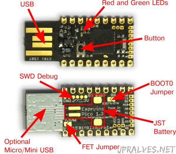
- USB Type A connection on PCB
- Two on-board LEDs and one button
- STM32F401CDU6 CPU - ARM Cortex M4, 384kb flash, 96kb RAM
- 3.3v 250mA On-board voltage regulator, accepts voltages from 3.5v to 16v
- Current spent in sleep mode: <0.05mA - over 2.5 years with a battery of 2500mAh
- On-board FET that can be used for high current outputs.
Installation on a Windows PC:
- Driver installation on windows 8.
- Download ST driver (STM32 Virtual COM Port Driver) at http://www.st.com/web/en/catalog/tools/PF257938#.
- Run the executable “VCP_V1.4.0_Setup.exe”.
- Once installed, go to the folder: “C:\Program Files (x86)\STMicroelectronics\ Software\Virtual comport driver”
- Depending on the 32-bit or 64-bit version run the command dpinst_x86.exe or dpinst_amd64.exe
- At this point there will be a new serial port (COM). Check the ID number through the “Device Manager”.
- Use terminal access software (Termite, Putty, etc.) - Parameters: 9600 bauds 8n1.
- You can also use the IDE that was written for Chrome - Espruino Web IDE
Now we can start writing code:
Write reset()
 _____                 _
|   __|___ ___ ___ _ _|_|___ ___
|   __|_ -| . |  _| | | |   | . |
|_____|___|  _|_| |___|_|_|_|___|
          |_| [http://espruino.com](http://espruino.com/)
1v75 Copyright 2015 G.Williams

setInterval("digitalWrite( LED1,l1=!l1);",200);
setInterval("digitalWrite( LED2,l2=!l2);",400);
Obviously many more examples can be explored … But that’s for another time.
Useful links: